Major Systems
Major Systems
Reactor Coolant System
The reactor coolant system of the pressurized water reactor (PWR) consists of a reactor vessel, steam generators, reactor coolant pumps, a pressurizer, and other elements. These principal components are interconnected by the reactor coolant piping to form a loop configuration.
Reactor Vessel
The reactor vessel consists of fuel and core support structures and is designed to form a reactor coolant pressure boundary that withstands the high temperatures and high pressures during normal operation, abnormal transient conditions, and fast-neutron embrittlement.
Steam Generator
The steam generator is a vertical U-tube heat exchanger that converts the thermal energy generated in the reactor vessel into steam and transfer the steam to the turbine system. The steam generator is placed higher than the inlet-outlet nozzles of the reactor vessel to enable the removal of decay heat by natural circulation upon reactor shutdown.
Reactor Coolant Pump
The reactor coolant pump circulates the reactor coolant, to remove heat from the reactor core at a constant flow.
Pressurizer
The pressurizer controls the reactor coolant system to maintain constant pressure, by actuating the electrical heater, spray valve, and relief valve.
Reactor Coolant System
The reactor coolant piping inter-connects the reactor vessel, steam generator, and reactor coolant pump into a circulating loop configuration.
Basic Specification
| 600MWe Class | 900MWe Class | 1,200MWe Class | APWR1,500MWe Class | |
|---|---|---|---|---|
| Number of Loop | 2 | 3 | 4 | 4 |
| Operating Pressure(MPa) | Approx. 15.5 | Approx. 15.5 | Approx. 15.5 | Approx. 15.5 |
| Operating Temperature(°C) | Approx. 300 | Approx. 300 | Approx. 300 | Approx. 300 |
Reactor Internals
Reactor internals of a pressurized water reactor (PWR) is a support structure installed in the reactor vessel to position nuclear fuel assemblies in a cylindrical arrangement.
The reactor internals structure consists of the upper reactor internals and the lower reactor internals.
Core and Fuel
A fuel assembly of a nuclear reactor core consists of an array of fuel rods and control rod guide thimbles bundled together and held with grids. The fuel rod is made from zirconium alloy cladding tubes containing cylindrical fuel pellets made from sintered UO2.
Since delivering the first nuclear fuel to Kansai Electric Power Company's Mihama Unit 1 in 1970, MHI has been providing high-quality nuclear fuel to a total of 24 plants owned by Hokkaido Electric Power, Kansai Electric Power, Shikoku Electric Power, Kyushu Electric Power, and Japan Atomic Power. Throughout this time, MHI has consistently worked on improving the design and quality of its products, which are now considered the highest in the world. Furthermore, MHI has been advancing the development of high burn-up fuel (MOX fuel) with the aim of enabling efficient use of uranium resources, as well as enhancement of the fuels as an integral part of power plants.
About MOX fuel
Mix oxide (MOX) fuel is a nuclear fuel for LWR plants, manufactured by mixing plutonium recovered from spent reactor fuel with uranium. Burning MOX fuel in the LWR reactor core is called "plu-thermal", combining the words "plutonium" and "thermal reactor" (thermal neutron reactor, generally referred to as LWR).
The implementation of plu-thermal is in compliance with Japan’s commitment to the efficient use of uranium resources and the national policy of not possessing excess plutonium, explicitly described in the Long-Term Program for Development and Utilization of Nuclear Energy of Japan. Mitsubishi group is working on a variety of areas, including design of MOX fuel, safety evaluation, core design, impact assessment on plant systems, design of transport containers, and fuel fabrication.
Track Record of PWR Fuel Production
Fuel Assembly and Control Rod Cluster (17×17 Type)
Basic Specifications of Reactor Core
| 600MWe Class | 900MWe Class | 1,200MWe Class | APWR1,500MWe Class | |
|---|---|---|---|---|
| Thermal Output(MWt) | 1,650 | 2,652 | 3,411 | approx. 4,451 |
| Core equivalent diameter(m) | 2.5 | 3.0 | 3.4 | 3.9 |
| Core active height(m) | 3.7 | 3.7 | 3.7 | 3.7 |
| Number of loaded fuel assembly(per core) | 121 | 157 | 193 | 257 |
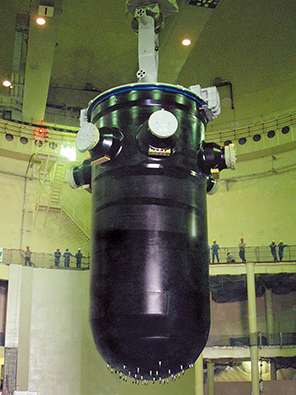
Reactor Vessel
The reactor vessel of a pressurized water reactor (PWR) power plant contains the nuclear core and requires the utmost reliability, to ensure safe use under extremely harsh conditions including high temperature, high pressure, and neutron exposure.
At MHI Group, we base the specifications of materials used for the reactor vessel on comprehensive test data. Large forged steel pieces are used to reduce welded parts, minimizing the amount of joints inspection required during the in-service inspections. Improved designs to the head adaptors of the reactor vessel have been applied to reduce residual stresses.
We have also enhanced the corrosion resistance of our upper reactor vessels and are supplying them globally to existing plants for preventive maintenance replacement purposes.
Specifications of Reactor Vessel
| 2 Loop | 3 Loop | 4 Loop | 4 Loop(APWR) | |
|---|---|---|---|---|
| Height(m) | 11.5 | 12.4 | 12.9 | 13.6 |
| Thickness(mm) | 168 | 197 | 216 | 255 |
| Inner Diameter(m) | 3.4 | 4.0 | 4.4 | 5.2 |
| Weight(ton) | approx. 240 | approx. 330 | approx. 410 | approx. 590 |
| Maximum Operating Pressure(MPa) | 17 | |||
| Maximum Operating Temperature(°C) | 343 | |||
| Material(Main Part) | Low-alloy steel(SFVQ1A,SQV2A,stainless steel cladding on inner surfaces) | |||
Steam Generator
Steam generators of PWR nuclear power plants produce steam and separate the reactor system from the turbine system. They play a crucial role in maintaining the reliability of the entire PWR plant.
Since producing its first unit in 1970 for the Mihama Unit 2, MHI has continuously improved the design of it steam generators. With our extensive experience, we have manufactured and delivered more than 100 steam generators, including replacement units.
Specifications of Steam Generators
| Model 54F | Model 70F-1 | ||
|---|---|---|---|
| Shell Outer Diameter | Upper shell(m) | approx. 4.5 | approx. 5.1 |
| Lower shell(m) | approx. 3.4 | approx. 3.9 | |
| Total Height(m) | approx. 21 | approx. 21 | |
| Heat Transfer Tubes | Number of tubes(No./Unit) | 3,386 | 5,830 |
| Outer diameter(mm) | approx. 22.2 | 19.1 | |
| Wall thickness(mm) | approx. 1.3 | approx. 1.1 | |
| Heat Transfer Area(m2/Unit) | approx. 5,060 | approx. 6,500 | |
| Weight(ton) | approx. 330 | approx. 440 | |
Reactor Coolant Pump
The reactor coolant pump is a rotary machine which circulates the reactor coolant at high temperature and pressure in a PWR nuclear power plant.
A reactor coolant pump consists of a vertical shaft and a single-stage suction diffuser with excellent hydraulic efficiency. MHI adopts non-contact controlled leakage system for the shaft seals to ensure reliability to support long and continuous operation. To support the ease of maintenance of reactor coolant pumps, we have introduced a cartridge type shaft seal in addition to improving the design and material specifications to extend the life of the seal. We are also developing a robot to be used to overhaul the reactor coolant pump seal. Our products undergo full flow tests in our facility to ensure their performance and integrity.
Specifications of Reactor Coolant Pumps
| 93A-1 | MA25S | 100D | |
|---|---|---|---|
| Pump Type | Vertical shaft, single stage, suction diffuser type, limited leakage seal system |
||
| Flow rate(m3/h) | 20,100 | 25,800 | 20,200 |
| Net Pump Head(m) | approx. 80 | approx. 88 | approx. 80 |
| Maximum Operating Temperature(°C) | 343 | ||
| Normal Operating Pressure(MPa) | 15.5 | ||
| Normal Operating Temperature(°C) | approx. 290 | ||
| Speed(rpm) | approx. 1,200 | approx. 1,200 | approx. 1,500 |
| Seal Water Flow(m3/h) | 1.8 | ||
| Thermal Barrier Cooling Water Flow(m3/h) | 9.1 | ||
| Motor Type | Drip-proof, squirrel-cage type, Flywheel with anti-reversal mechanism | ||
| Power Source(Frequency(Hz)/Voltage(V)) | 60/6,600 | 60/6,600 | 50/6,600 |
| Motor Power(kW) | (nominal)4,480 | (nominal)6,000 | (nominal)4,570 |
| Pump Efficiency(%) | 83 | 85 | 83 |
Turbine Generator System
The key elements of the turbine-generator system of the pressurized water reactor (PWR) are turbines to convert thermal energy generated by the steam generators to kinetic (rotation) energy and a generator to convert the kinetic energy into electric energy.
Low-Pressure Turbine Last Stage Blades
To convert thermal energy into kinetic energy effectively, the lengths of the last-stage rotating blades can be selected from 41, 46, and 54 inches for half-speed, low-pressure turbines (60 Hz).
Steam Turbine
High-Pressure/Low-Pressure Turbine
The fully three-dimensional blades and long blades boost the efficiency of the turbine system in converting thermal energy to kinetic energy. The integral shroud blades (ISB) enhance the reliability of the turbine system.
Long Blade Design for Improved Output
The stator coils of the generator are cooled with water and the rotor coils are cooled with hydrogen. The generator has a "top hat" structure comprising a hydrogen gas cooler mounted on the frame of the generator. This structure enhances the stability and reliability of the shaft system by reducing the length of the rotor.
The exciter is a brushless type with a long history of service and reputation for easy maintenance. It is driven by the turbine to reduce in-house electricity.
Generator and Exciter
The steam flow rate into the turbine with lower-pressure/wet steam is much larger than that for conventional power plants. Long- blade(41-54in.)/half-speed machines are used for nuclear applications.