The ML5 Movable Launcher Watching over a Journey to Space: The Mechanism Supporting and Releasing the H3 Rocket
Story1
The Launcher That Supported the H-IIA Rocket for a Quarter Century with a Success Rate of about 98%
Moving the Assembled Rocket to the Launch Pad
Artificial satellites that deliver information closely tied to our daily lives—such as weather and positioning data—are sent into space by rockets. Japan’s rocket-related technologies are known for their high reliability, and among them, the H-IIA rocket boasts an exceptionally high success rate of about 98%.
It has been in operation for 24 years since 2001, and with the launch of its 50th vehicle on June 29, 2025, it was officially retired.
The ground facility that supports large liquid-fueled rockets from assembly through launch, such as the H-IIA and its successors, is the Movable Launcher, commonly known as the "ML.
"Mitsubishi Heavy Industries Machinery Systems (MHI-MS) has been responsible for the design and manufacture of these MLs, contributing significantly to Japan’s space development efforts.
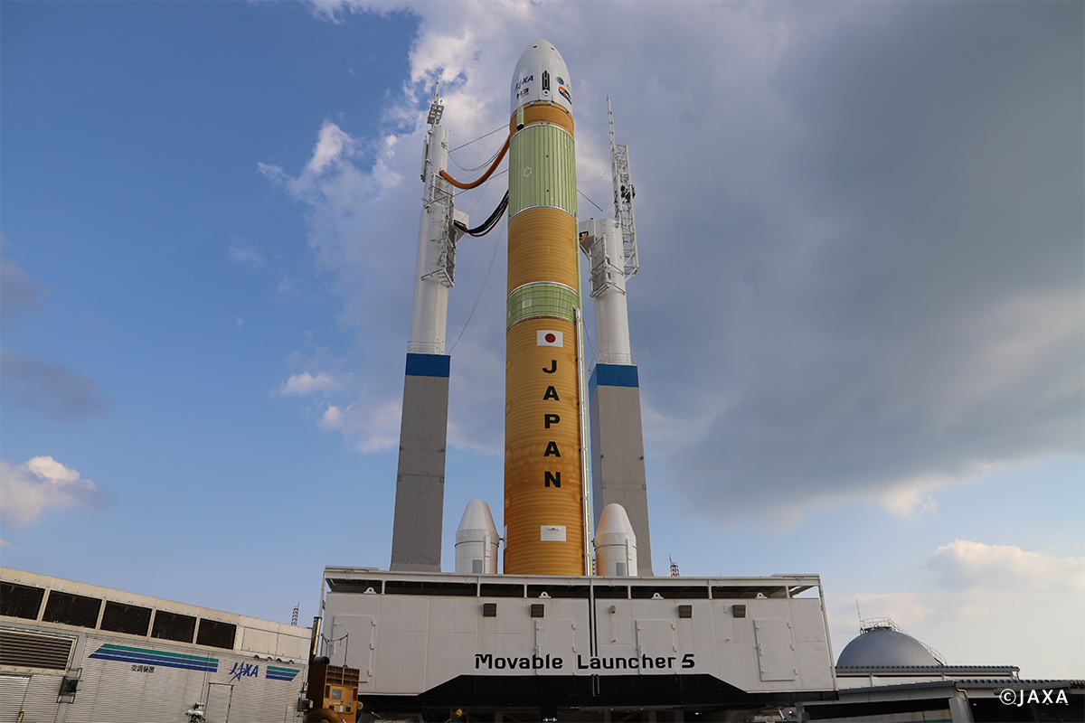
As its name suggests, the ML serves as the launch platform at liftoff. Prior to launch, it is moved to the launch pad, where propellants such as liquid hydrogen and liquid oxygen, as well as electrical power, are supplied to the rocket via the platform, and final checks are conducted. In addition, it also functions as the base for assembling the rocket’s first and second stages, the payload fairing, and the solid rocket boosters (SRBs) that are transported to the Tanegashima Space Center.
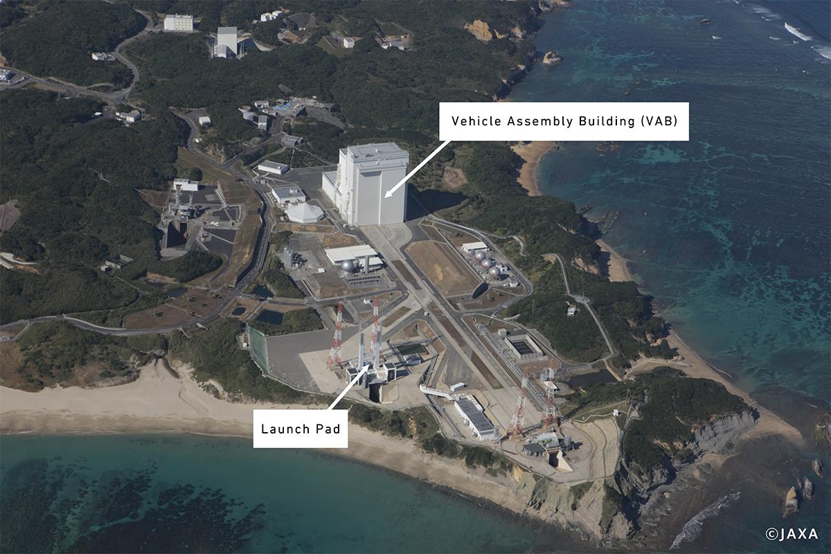
For safety reasons, the Vehicle Assembly Building (VAB), where the rocket is assembled and serviced, is located approximately 500 meters away from the launch pad. The entire launch platform, with the rocket mounted on it, is transported between the two by a dedicated large transport vehicle known as a dolly.
The "Umbilical Hose" That Supplies Fuel
The history of movable rocket launchers in Japan dates back to the H-II rocket, the core launch vehicle of the generation preceding the H-IIA rocket.
With the development of the H-IIA rocket, the current system, under which the rocket is moved together with the launcher, was adopted, and ML1 and ML3 were put into service. Furthermore, to support the H-IIB rocket whose capabilities were enhanced from those of the H-IIA rocket primarily for launching the HTV for space station resupply missions, ML3 was modified and put into operation.
The structure of the ML series can be broadly divided into two main components.
The main body, which serves as the base supporting the rocket, is 22 meters in width and 25.5 meters in depth.
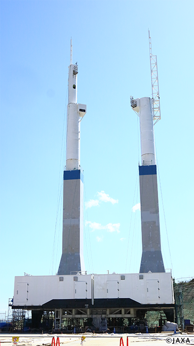
The mast that supplies fuel and other services stands approximately 66 meters tall and also functions as a lightning rod; it is commonly referred to as the umbilical mast.
Until just before liftoff, the rocket and the launch platform are connected by these umbilicals, which are disconnected at the moment of launch. From the moment the rocket takes shape through its departure on its journey, the ML continues to watch over it—truly fulfilling a role akin to that of a mother for the H-IIA and H-IIB rockets.
Story2
Developing a New Launcher to Support the Missions of the H3 Rocket
Aiming to Strengthen International Competitiveness
Plans for a next-generation large core rocket began in 2014. Led by the Japan Aerospace Exploration Agency (JAXA) and Mitsubishi Heavy Industries, development of the H3 rocket progressed.
Following conceptual design work on the rocket itself, MHI-MS also began full-scale detailed design of a new ML in 2016.
This marked the first new development of a core rocket since the H-II rocket, roughly 30 years earlier. A major objective of this project was to strengthen the international competitiveness of Japan’s rocket launch services.
While the H-IIA/B rockets were highly regarded for their reliability, overseas competition on cost was intensifying, with the rise of private-sector launch providers. To expand orders from customers seeking satellite launches, it became essential to improve competitiveness by shortening launch preparation periods and reducing costs.
The new ML designed for the H3 rocket was also therefore required to achieve lower launch and maintenance costs while building on the reliability and operational expertise accumulated to date.
The fundamental development policy was to enhance operability and maintainability. By simplifying the overall system design, the goal was to balance low cost with high reliability, while maintaining a high level of operability capable of supporting up to six launches per year.
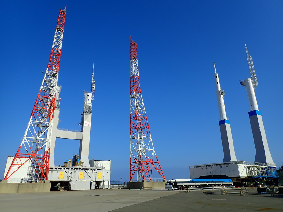
In the photo, ML3 is on the left, and ML5—then under assembly—is on the right.
Passing on Technology through the First New Development in 25 Years
At the same time, the development of the H3 rocket also carried the mission of maintaining Japan’s technological and industrial capabilities so that the country can continue to possess independent means of access to space into the future.
For MHI-MS as well, it meant passing on the technologies that support rocket launches to the next generation.
Looking back, G.S., who was in his mid-20s at the time and participated in the design of the new ML, recalls: "It had been 25 years since the development of ML1, and almost none of the members from that time were still around.
The engineer who had been responsible for the design of ML3 served as the project manager, and we moved forward with development while coordinating closely with our customers (JAXA and Mitsubishi Heavy Industries).
We proceeded by rigorously checking each and every process from a critical standpoint, and I myself was challenged and trained a great deal through the experience. I learned the importance of thinking carefully about what the customer truly wants, and then incorporating that understanding into drawings and calculations."
Story3
What the Rocket Breaks through is Not the Ceiling, but the Launcher
Challenges in Using Existing Facilities
In terms of appearance and size, the completed movable launcher for the H3 rocket, ML5, is almost unchanged from the previous-generation ML3. The most noticeable change in its external appearance is the mast. Its upper section has been changed from a rectangular column to a cylindrical shape, and the over-bridge that once connected the two masts has been eliminated. These changes are the result of wind tunnel testing and simulations, through which the design was optimized to minimize the impact of wind striking the mast on the rocket’s airframe.
The lack of major changes in overall size stems from the decision to make use of existing facilities at the Tanegashima Space Center that already have a proven track record and established reliability. Because the VAB and launch pad used for the H-IIA/B rockets would continue to be used with only minimal modifications, ML5 had to be sized so that it could be housed inside the VAB. This policy of leveraging existing facilities, however, introduced a significant challenge in the design of ML5. Rockets are assembled in an upright position inside the VAB, and the H3 rocket has a maximum overall length of approximately 63 meters, which is 6 to 10 meters taller than the H-IIA/B rockets. If it were placed on top of the ML main deck, which stands about 7 meters high as before, the rocket would break through the ceiling of the VAB.
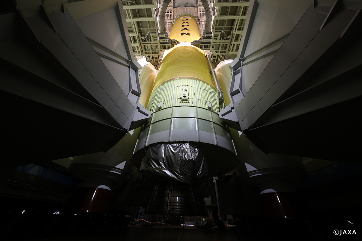
The solution was to position the rocket so that its body passes through the ML deck itself.
Conventional MLs already had an opening to allow the exhaust plume from the engines to pass through during launch, and this opening was expanded. As a result, rocket assembly could continue to be completed entirely inside the VAB, just as before.
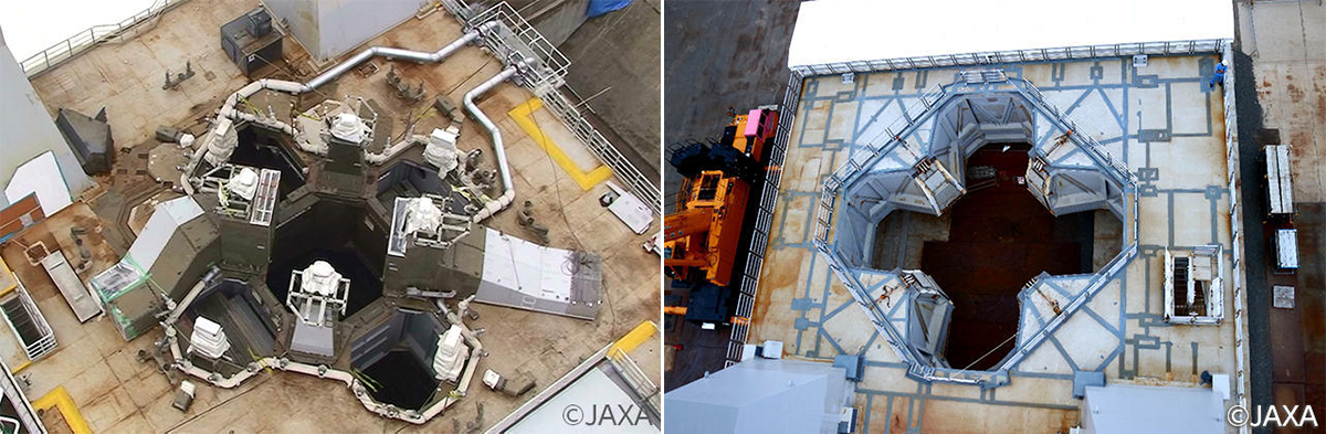
Figure: Top surface of the launch hold-down platform
The launcher on the left is the conventional one (used for the H-IIA/B), while the one on the right is for the H3. The opening on the top surface has been enlarged, and the design has been improved so that no equipment is exposed on the platform’s upper surface.
Balancing Cost and Reliability through a Simple Structure
Enlarging the opening in the ML main deck provides additional benefits as well. Allowing exhaust gases to flow out more freely through the opening reduces the noise generated by the plume, which in turn helps mitigate the impact of acoustic waves on the rocket and the onboard satellite equipment.
In addition, thermal damage to the ML caused by engine exhaust has been reduced. This has decreased the amount of post-launch repair work required for damaged areas, thereby contributing to shorter intervals between launches.
Furthermore, with the reduction in exhaust-induced noise, the mechanism that suppresses sound by flowing water across the deck to generate steam could also be simplified.
"There was no longer a need to install water piping on the ML deck, and the equipment that injected water into the exhaust duct—previously located on the lower deck—was moved to the launch pad side. The more complex the structure of the launcher becomes, the more those complex parts generate noise, and the larger the areas that suffer thermal damage. How far we could simplify the structure was one of the major themes of ML5," G.S. explains.
Because the rocket now passes through the deck, a new, extremely simple support method was adopted; Instead of supporting the rocket body on the top surface of the ML main structure as before, four launch hold-down fixtures were newly installed on the sides of the enlarged opening.
Two major requirements were set for this.
The first was to ensure that, during liftoff, the hold-down fixtures would not interfere with the rocket’s motion or cause excessive thermal damage to the ML.
The second, from the perspective of reliability, was to avoid using electrical power for the operation of the hold-down fixtures as much as possible.
Story4
Answering the Question: "How Do You Keep the Rocket Stable?"
A Retraction Mechanism Based on Classical Mechanics
"The launch hold-down fixtures have a shaft and rotate like a lever. Once the rocket engines ignite and the load is released, they swing around and retract into the ML, and then the top cover closes."
As O.M., who worked on the modifications to ML5 in preparation for launch, explains, the launch hold-down fixtures that support the rocket can be stowed within the sides of the ML opening. This allows them to avoid contact with the ascending rocket while also protecting themselves from the engine exhaust plume.
The mechanism that retracts the hold-down fixtures had to avoid the use of electricity or sensors.Instead, what was adopted was a simple motion based on classical mechanics—something that could almost be described as a purely mechanical "trick."
However, the timing of the retraction was subject to extremely strict requirements.
Each launch hold-down fixture weighs about 10 tons, and to suppress the impact when it completes its rotation, a hydraulic damper was installed inside. In addition, the rotating bearings are doubled, ensuring redundancy so that the system can cope even with the unlikely event that one bearing fails to rotate.
"High repeatability and precision are required for the rotation of the hold-down fixtures, so we conducted dozens of tests to confirm that the same motion could be achieved every time during launch. It was particularly challenging for the designers to go to the factory and verify whether the actual behavior matched the calculations," G.S. says.
A New Mechanism to Support New Rocket Configurations
The final major challenge in supporting the rocket was accommodating variations of the H3 rocket.
Conventional H-IIA/B rockets were equipped not only with a liquid rocket engine but also with two or four solid rocket boosters (SRBs) arranged around the core stage. By contrast, to meet a wide range of launch requirements, the H3 rocket is also planned to operate in its minimum configuration, the H3-30S variant, which uses three liquid rocket engines and no SRBs.
The SRBs also served as ballast, helping to prevent the rocket from lifting off in an unstable manner.
"In the 30S configuration, the vehicle itself is lighter, so it has to be restrained from above until just before liftoff, when sufficient thrust is produced after the three engines ignite," O.M. explains.To address this, ML5 adopted an additional "hold-down system" attached to the launch hold-down fixtures.
This system uses a structure in which the rocket is supported from below by the rotating launch hold-down fixtures and clamped from above by the hold-downs. When the thrust from the three liquid rocket engines becomes sufficient, the hold-downs are released, allowing the rocket to lift off.
The system has already been installed, and while it has not yet been used at the moment of liftoff in H3 rocket launches to date, applying the hold-downs during ML5 transport and in normal standby conditions contributes to improved rocket stability.
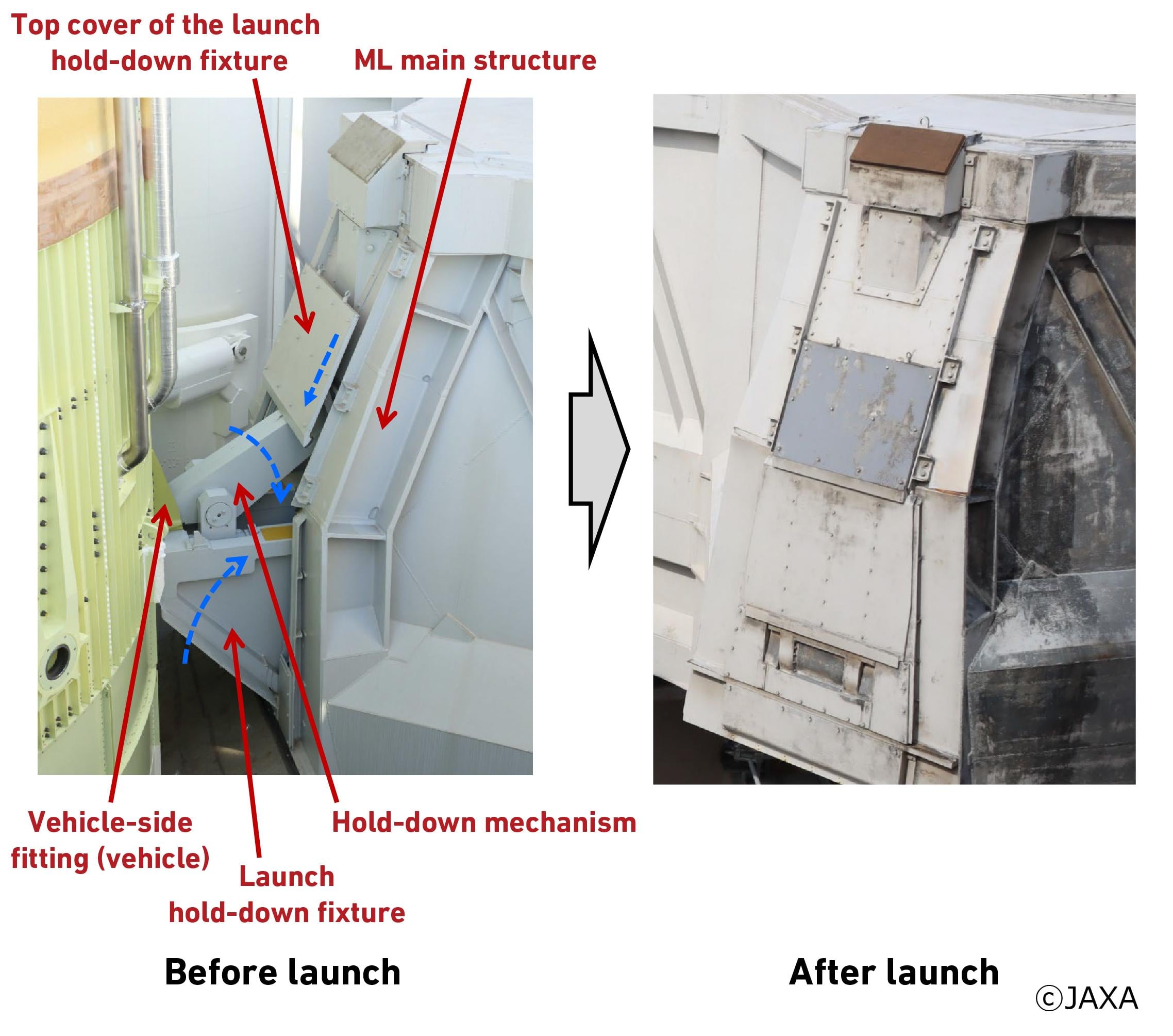
Image adapted from JAXA press briefing materials on the H3 Launch Vehicle development status and the combustion test (CFT) of the first-stage full-scale tank test stage of H3 Launch Vehicle Flight No. 6 (30-configuration test flight)(original document in Japanese).
Story5
Technologies Expanding from Space—and Technologies Expanding toward Space
ML Know-How Applied in Other Fields
By fiscal year 2024, launches of the H3 rocket had been completed up to Flight No. 5. All of the vehicles launched so far have been in the H3-22S configuration, using two SRBs. The next step for ML5 is full-scale operation of the hold-down system for the H3-30S configuration.
In addition, preparations are under way to support the H3-24 configuration, which accommodates a large fairing for launching the next-generation space station resupply vehicle (HTV-X). (As of the time of the interview.)
It is often said that technologies related to space readily find applications in other fields.
G.S. comments, "At our company, we are working to break down the barriers between conventional product lines and to apply the knowledge and expertise cultivated in one product area to other fields as well. Large steel structures like the ML are relatively rare, and the know-how gained from them will undoubtedly prove useful. I also believe that the high standards demanded for quality control will increasingly be required in other product areas going forward."
Keeping the Space Dream Alive
Meanwhile, the diverse product technologies possessed by MHI-MS are being actively applied in the space industry as well.
MHI-MS is also responsible for replacing aging tanks and piping at the Tanegashima Space Center, work in which O.M. is involved by leveraging pressure-vessel design and manufacturing technologies originally developed for marine products.
"What our customers expect from MHI-MS is technical capability. I’m always conscious of the need to deliver work they can trust with confidence. By steadily building on the trust earned through ground-facility projects, I personally hope to become involved in developing product technologies that can eventually be used in space itself," says O.M.
Human spaceflight using rockets launched from Japan, and the reuse of rockets—dreams of space are endless.
Turning those dreams into reality requires a wide range of technologies and innovations. The technologies of MHI-MS, inherited and further evolved by young engineers like them, are sure to continue paving the road to space.
Development Story
Next-Generation Multistory Parking Lot installed underground in the inner-city - Birth of the Mitsubishi Cell Park (Two-Lift Type) -
From the site of MC development, a new corrugated board box making machine that is responsible for the production of corrugated boxes that supports our lives and economy